S3 Design basic circuits using discrete components

I have marked this section of the audit as a '1' meaning little knowledge if not any at all.
__________________________________________________________________
__________________________________________________________________
What I have learnt and what I understand now
Following our taught session today I realised that actually there is no difference between a component and a discreet component. I learnt that discrete merely means that it is separate meaning that they have a single function and that the electronic components can be selected individually and put together in order to create a circuit. I was able to identify that every component used in a circuit has a specific use and each role is important in order for the circuit to work.
I now understand that examples of discrete components include;
- Resistors
- Capacitors
- Diodes
- Transistors
At the moment there is quite a great deal to take in because there are so many components to consider when designing a circuit. Today we were taught how to make a PCB and once we had finished this process we then began to build our circuits for the systems and control module. It was at this point things seemed to become much more clearer.
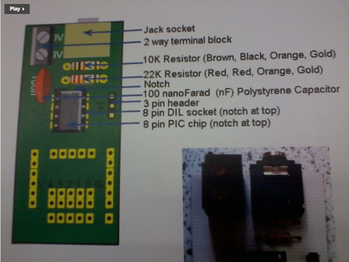
What I realised in time and learnt was that although there are a range of components that serve different roles within a circuit, as a circuit builder you tend to use a selection of the same ones in order to build any functional circuit. So for instance you would always use a resistor or a two way terminal block. I was able to understand this because of the mock sheet (image shown to the left) this acted as a guide whilst we were building our individual circuit - even though many of us were thinking of building different products we all needed the same components in order for the circuit to work. Therefore, from my understanding now I can see that some components are universally used when building and designing a circuit.
What I realised in time and learnt was that although there are a range of components that serve different roles within a circuit, as a circuit builder you tend to use a selection of the same ones in order to build any functional circuit. So for instance you would always use a resistor or a two way terminal block. I was able to understand this because of the mock sheet (image shown to the left) this acted as a guide whilst we were building our individual circuit - even though many of us were thinking of building different products we all needed the same components in order for the circuit to work. Therefore, from my understanding now I can see that some components are universally used when building and designing a circuit.


The images above illustrate the components that I have used for my circuit board. The image on the left shows the early stages of a circuit board that everyone would have started with in the class whilst referring to the guideline sheet. The image to the right shows the components that I have added specifically for my project later on in the module.
The components that I have used here are:
Later on through this process of engagement I learnt and realised that discrete components can also be used as components in circuits that include an integrated circuit. For example, a PIC Chip will require two discrete resistors and a discrete capacitor to make it work. PIC chip's are mini circuits that have been etched onto silicon and you programme the chip using code and it then controls the inputs and outputs.
__________________________________________________
The components that I have used here are:
- Two LED'S
- Resistors
- LDR
Later on through this process of engagement I learnt and realised that discrete components can also be used as components in circuits that include an integrated circuit. For example, a PIC Chip will require two discrete resistors and a discrete capacitor to make it work. PIC chip's are mini circuits that have been etched onto silicon and you programme the chip using code and it then controls the inputs and outputs.
__________________________________________________
Analysis of new gained knowledge and the next step
Before I approached this area of the audit I had no clue what so ever as to what a component was or the processes in which you take in order to design a basic circuit. For this reason, I initially marked this area as a '1' meaning little knowledge if not any at all, but through my own engagement and also during the taught sessions I have realised that this section of the audit is not as scary as it may first seem. I can confidently say that I am now comfortable in designing a basic circuit that uses discrete components and hopefully I have been able to demonstrate my deeper understanding within this part of the audit.
I felt most successful as a learner when I was following a guide that had already been prepared by Dean. Learning about the components did really helped and it introduced me to the principles and I feel that being able to touch and look at what your learning is always going to help in anyone progression. Using Dean's guide also enabled me to realise and identify that there were common components that were used in the process of making a circuit, I feel as a leaner it is crucial to become aware of these common concepts, as it helps you to not only translate this information to students in the future but also apprehend the area even further which in turn supports your development.
Initially, the thought of designing a circuit was somewhat frightening and I became quite bogged down quickly at the amount of components that were available to us. In retrospect, I feel that this is a negative aspect of my learning because I should not get too knocked or disheartened when approaching a new area with lots of content. The main thing that I need to remember is that breaking it down into chunks and learning through engagement is going to facilitate my learning and progression furthermore, looking at other sources such as Bitesize or revision guides will help to break down and tackle the principles of the area. However, as I have mentioned before I am conscious of using these sources such as Bitesize as a primary source of learning because I feel you can become quite lazy whilst learning if you continue to use this as your soul or only learning tool.
Even though I have already designed and built my basic circuit using components I feel that there is more to learn in this area so hopefully through the course I will be able to move further forward in my knowledge. If I do not come across this again in my future projects then it will be useful to refer back to this and see if I am able to learn anymore. At this moment in time I think that what may be useful to know and learn is the basic any further basic principles and common concepts that are used during this process of the audit. Whats more, I could also create a visual aid or guideline for me to learn from in the future when designing circuits at least I am then able to refer back to it in my career.
__________________________________________________

Further Development
Now that I have handed in the systems and control project I have realised that I have in fact learnt more and now can appreciate the importance of this as an initial stage of any electronics project. I am now aware that the designing stages are so crucial because like any product if it is not designed well then it is not going to work properly, also the components need to be handled with care especially whilst building the board and I now know that you should really test circuits before you begin to solder components. Drawing circuit diagrams and creating visual aids can contribute to a circuit being designed well and avoid faults. Also I have realised that now there are even more principles that you can use when designing a circuit with basic components. SO when designing a Circuit.....
These further principles were factors that I learnt and realised once I had finished my work, I noticed these concepts whilst I was evaluating and reflecting my product, I was thinking about things that I could have done better and aspects that continued to crop up related back to the early processes of designing and using the components. If you insure that you are sticking to these principles then it can avoid any which saves time, but most importantly it contributes to the circuit being a better functioning design.
Furthermore, I did decide later on to create a visual aid in order to help me in the future if faced with a project like this again. It also insures that I do not make any mistakes during my designs. Although not every project will be the same this is a good guide line like Deans from the first sessions that can help me progress and develop future projects.
Below you can see this visual aid. I created this using Adobe Illustrator.
Now that I have handed in the systems and control project I have realised that I have in fact learnt more and now can appreciate the importance of this as an initial stage of any electronics project. I am now aware that the designing stages are so crucial because like any product if it is not designed well then it is not going to work properly, also the components need to be handled with care especially whilst building the board and I now know that you should really test circuits before you begin to solder components. Drawing circuit diagrams and creating visual aids can contribute to a circuit being designed well and avoid faults. Also I have realised that now there are even more principles that you can use when designing a circuit with basic components. SO when designing a Circuit.....
- The components need to be put in the correct sections on the board so they can be powered
- You need to be aware of your inputs and outputs and where the components go in relation to the circuit and the tracks
- Your understanding of where your inputs and outputs go in relation to the positive and ground volts is another important factor
- The components legs or leads need to be bent apart and not touching each other, if not then this can cause fault but also insures that the components do not fall out
- Once soldered the leads of the components need to be trimmed with a cutter
- The components need to be flat against the board
- If you can see a hole in the board where the lead of the components goes through then there is not enough solder
These further principles were factors that I learnt and realised once I had finished my work, I noticed these concepts whilst I was evaluating and reflecting my product, I was thinking about things that I could have done better and aspects that continued to crop up related back to the early processes of designing and using the components. If you insure that you are sticking to these principles then it can avoid any which saves time, but most importantly it contributes to the circuit being a better functioning design.
Furthermore, I did decide later on to create a visual aid in order to help me in the future if faced with a project like this again. It also insures that I do not make any mistakes during my designs. Although not every project will be the same this is a good guide line like Deans from the first sessions that can help me progress and develop future projects.
Below you can see this visual aid. I created this using Adobe Illustrator.

Professional Year Further Development
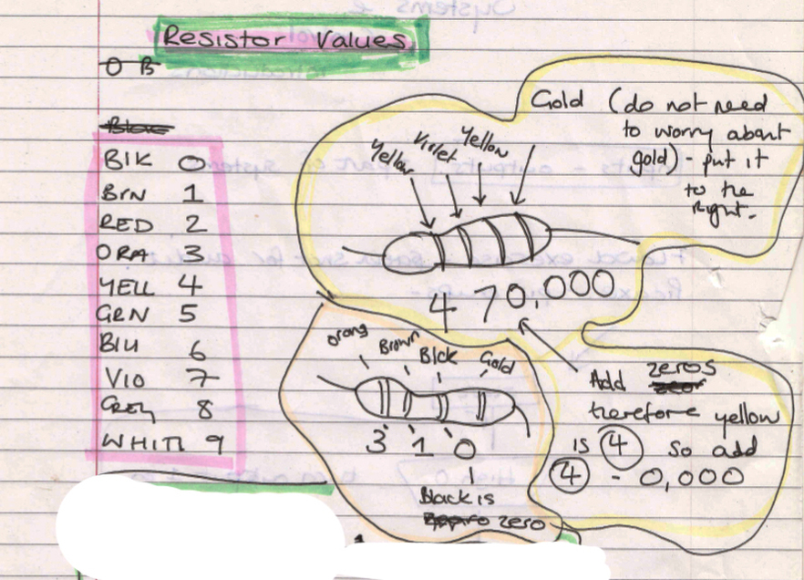
Today we had a introduction and a revision session in Systems and Control. I found it most useful to revise the resistor values as this was an aspect of Electronics that I found at times confusing. I find it now however pretty straight forward and I have added my notes that I made in class just in case I need to refer to this again in the future.
Things to remember!!!!
Today exploring and experimenting with electronics I revised a few important points to consider when building your circuits. Some of these points are included throughout the audit however I wanted to just recap it here as well.
- All LED'S use 470r Resistors.
- LDR'S use 10k
- Components- one to ground and one to the resistor - positive always goes to the resistor.
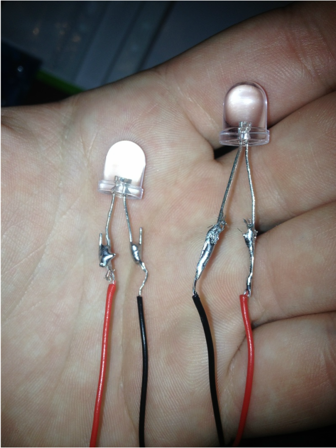
At school today I started to make one of the electronic projects that the year 7's had been set. One of the teachers showed me a different way of soldering the LED'S to the wires so I thought I would add it on here to remind me in the future. The example on the right was the method I used to connect the component and the left is a method that the teacher showed me.
This is an example of a basic digital circuit that I have built at school which is part of the YEAR 7 torch project. It has helped me to learn more about how the system works and why the components are placed on the board in order for it to work properly. I need to add the switch but once it works I shall also add more images of the development.


