S6 Use prototyping techniques for testing circuits

This area of the audit has been marked at '1' meaning very little knowledge if not any at all.
___________________________________________________________________
What I have learnt and what I understand now
Never before have I used prototyping techniques to test a circuit. However, in my electronics project for systems and control there were points where I did explore these methods. Now not only have I learnt how to test my circuit, I can now understand the importance and purposes of undergoing these procedures and is a vital part of your development within any systems project.
Never before have I used prototyping techniques to test a circuit. However, in my electronics project for systems and control there were points where I did explore these methods. Now not only have I learnt how to test my circuit, I can now understand the importance and purposes of undergoing these procedures and is a vital part of your development within any systems project.
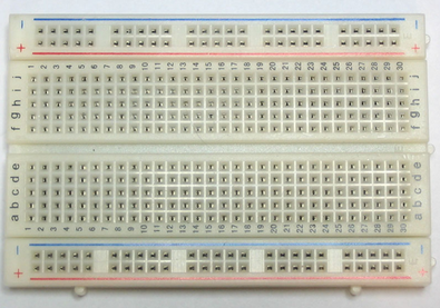
To begin with I needed to make sure that I understood that the the most common way to test a circuit is to use a breadboard or protoboard ( an example of this can be seen above). I now know that this board enables a user to assemble electronic components without having to solder or damage the components. The way I look at it is that a protoboard is a trail board for you to experiment and try out your circuit before actually building the final piece. Firstly, I needed to come to terms with how the board actually works, I learnt in the taught session today that the board has groups of little sockets or holes which are interconnected under the board. Components and wires can fit into these socket very easily which in turns enables a current to flow which then creates a circuit. The two rows of sockets running the length of the board are normally used as supply rails. The top and bottom rows are linked horizontally all the and the power supply is connected to these rows, + at the top and 0V (zero volts) at the bottom. I felt that I generally understood the principles fairly quickly so I noticed that it was a nice quick step in my development within this area of the audit.
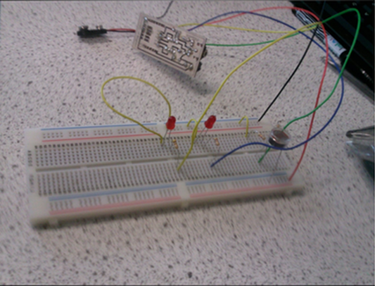
This picture on the left shows me trailing my circuit with all of the wires, and components in place. I only completed this process once all of my programming was finished and downloaded to the PIC.
We had already been introduced to breadboard testing within a taught session and therefore I referred to my notes to refresh my memory about how the board works.
To recap I made note of the important principles to consider and remember during this process. The RED and BLACK wires represented the + and - or ground, and the rest of the wires allowed me to categorise and distinguish the different electrical components.
Overall, this was an extremely useful task for me to undergo and I learnt a fair amount. Once I got my head around how the board worked and where to put the components I found that it really helped me to insure that my soldering was in the correct places to avoid mistakes. I was also then able to understand more about how my circuit would work and it also allowed me to see the circuit communicating and working with the code that had been programmed onto it. It also reminded me that every component that we use plays such a vital role in a circuit and determines whether or not the whole circuit will work properly. One mistake can cause the whole circuit to not work and that is why I realised that this is a very vital and useful process to take whilst building and designing any system. It also made me appreciate and understand that the chip is the central part of any circuit and needed to be connected to both the plus and ground volts. In addition, it must be handled with care and when connected to the power supply it needs to fit in the correct socket otherwise it will blow and then will not work. (I made this mistake a number or times and needed to get a chip!)
The main aspect that I liked about the proto board process was that it was very easy to move components about which meant that if something was wrong you could keep testing it in different places and find the fault quite quickly. For this reason, I felt that I was developing a better understanding quite quickly and moving on with my progression in the project at a nice pace as well. What also helped me to develop within this process was using different coloured wires, it allowed me to separate the different inputs/outputs, recognise the plus and ground volts which all in all create a systematic order which supported my learning and understanding in the operation of the circuit and task at hand. Like most learners, I think and learn better visually, and I am able to develop further especially when tackling a unknown area like electronics.
To conclude, this was also certainly good preparation for me to then begin soldering the components and make any adjustments if necessary however my circuit worked absolutely fine first time so I was quite lucky! - but it was important regardless of whether there were any problems that I went through the process of testing the circuit. I now can appreciate the importance of prototyping and will use this within my work in the future.
Other methods of prototyping
This picture was a visual aid that I used within my electronics project. In some respects it does not test the my circuit but it does act as a prototype and represents the PCB. I created this image using adobe Illustrator.
The main reasoning for me doing this was because I wanted it to be a visual source that would help me understand more about my board and how it works. It also was useful for me to have a detailed diagram like this because it avoided any soldering mistakes which if made could have potentially wasted valuable time during the project. In some respect this not only is a visual aid but also a set of instructions for myself that guide me when soldering all of my components to the board. I did find myself learning better when I used a visual aid that Dean provided at the start of the year.
The main reasoning for me doing this was because I wanted it to be a visual source that would help me understand more about my board and how it works. It also was useful for me to have a detailed diagram like this because it avoided any soldering mistakes which if made could have potentially wasted valuable time during the project. In some respect this not only is a visual aid but also a set of instructions for myself that guide me when soldering all of my components to the board. I did find myself learning better when I used a visual aid that Dean provided at the start of the year.
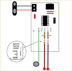
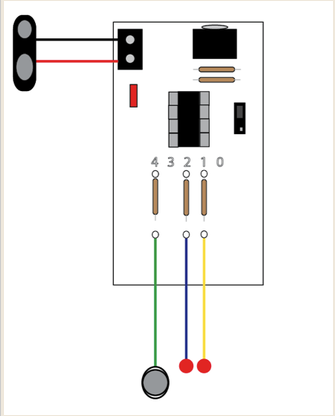
I realised later on that I had made a bit of a mistake with my initial visual aid (above) that I created. The LED's and resistors were in the correct place however, the LDR was in fact in the wrong place and I should have referred to the digital circuit that I designed using circuit wizard when designing this visual aid in the first place. The thing that I got wrong was not put into consideration that there was a potential divider within the circuit.
This potential divider would need to allow the LRD to connect to the plus voltage and the chip, it also needed to include a 10k resistor is which connected to the chip and the negative or ground voltage. There was not enough room for me to do this on my board and I was not sure whether I would need to actually need to make another board or whether there was a way for me to do this using the PCB board I had. asked for help and because of this everything has been made a lot more clearer.
As a result of this here is my final visual aid that I have created using Illustrator. It serves exactly the same purpose as the previous visual aid and it is something that I can refer to later on in the process to avoid any soldering mistakes but also it can be a useful source for revision for any future projects.
In general creating these visual aids was a worthwhile experience as it made me grasp a better understand of how the circuit will work but also it saved me time. Therefore, if I was to use prototyping techniques this would be a method that I shall use again because for me it help with my learning and progress.
___________________________________________________________________
Analysis of new gained knowledge and the next step
When I first approached this section of the audit I graded the area as a '1' translating to very little knowledge if any at all. I have found that through my own experimentation and exploration I was able to really come to grips with the concept of using prototyping techniques to test my circuit and through this audit I have not only displayed my development but also illustrated the importance of this process.
One reason as to why I felt that I was successful during this time within my learning was because I did not need to rely on any other source to support my development. In the past with the unknown areas of the audit I have used Bitzesize or looked at books to help develop my understanding. By no means am I saying that these are not valuable and worthwhile sources to support development, I just feel that they should not be the only and primary source that helps to support someone's learning. My reasoning for stating this is that you can normally learn simply by experimenting with the content and in regards to this I was able to learn more looking at the board, playing around with components and figuring out what it did and why it worked than sitting down looking at a book. I know that some areas of the audit are not necessarily practical and generally theory based, but setting yourself exercises and challenges within the area can help you to learn more and I shall take this with me for the rest of the time on the course whilst approaching new knowledge in the audit.
In addition, I felt that I was successful when I created my own visual aids to help me when soldering the components and building the circuit. Although some would say that they are a pointless source I found it very useful to refer back to when building my final board. I felt that they were a good way to prototype your designs and I also felt quite pleased with myself once I had identified that I had made a mistake and once I had realised this I created another visual to address the matter. I think that this just displays to me my progress and evidence of my deeper understanding within the area.
Perhaps I was least successful during this in terms of developing my knowledge even further with engaging and exploring other types of circuits using a protoboard. If I experimented with other types of basic circuits, instead of only concentrating on my own designs then I would have been able to understand the processes and the principles of systems and control even further. However, in defiance to this you can create basic circuits using software, these simulations can help and are great to aid development but I think the advantage with a protoboard is that you are actually touching and working with the components in your hand.
My next step now is to see if I can engage with any more ways in which to test my circuit. I know that Dean has mentioned that there are other useful techniques that you can take in order to avoid mistakes so I hope to dig deeper and use this within my work.
___________________________________________________________________

Further development
Now that I have progressed further within my project in systems and control I have come across other ways in which to test your circuit. I have learnt that you can simply complete some visual checks first and this can be a process which contributes to fault finding. So in some respects both areas are linked but it can also be used as a prototyping techniques because you are essentially testing the circuit. These checks could be:
I have learnt that this can really help save some time and will allow you to understand if there are any problems with your circuit. I found that there were a few issues with my work and therefore with Dean we went through the necessarily checks to test the circuit.
It reminded me how important it is when you are building and soldering your work, each component is important and the soldering needs to be perfect for it all to function.
Now that I have progressed further within my project in systems and control I have come across other ways in which to test your circuit. I have learnt that you can simply complete some visual checks first and this can be a process which contributes to fault finding. So in some respects both areas are linked but it can also be used as a prototyping techniques because you are essentially testing the circuit. These checks could be:
- Making sure the components are pushed soiled into the holes
- Checking wires have been cut and trimmed properly
- Insuring that all the components are the right way round and flat against the board
- Making sure that the components legs / leads are not touching each other
- Cleaning tracks and checking to see if they are clear for the current to flow
- Having a look at the PIC chip to see if the legs are in place and not bent out of shape
- Are the components solider correctly and have enough solder in the joints?
I have learnt that this can really help save some time and will allow you to understand if there are any problems with your circuit. I found that there were a few issues with my work and therefore with Dean we went through the necessarily checks to test the circuit.
It reminded me how important it is when you are building and soldering your work, each component is important and the soldering needs to be perfect for it all to function.
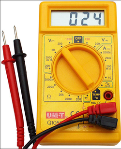
I have also used multimeter to help me test my circuit. I learnt that when measuring a resistor values, that you do not hold both ends of the resistor in your fingers or your body because the resistance will be measured in parallel with the value you are trying to measure.

Professional Year Further Development
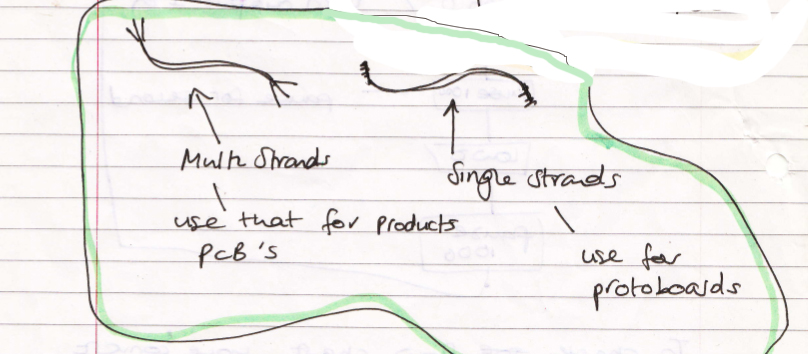
Today we had a quick introduction to Systems and Control. Something that I did not realise but now know is that you should always use a different wire when prototyping and building a circuit. Below the scanned image from my notes explains this.
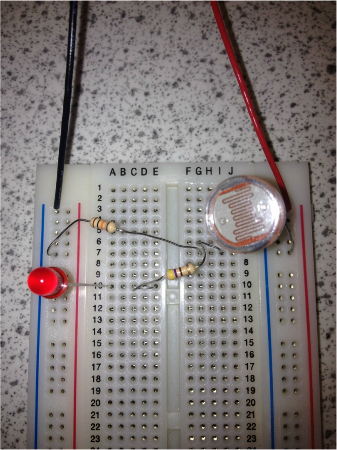
In some free time today I wanted to revise the protoboard and remind myself how it worked. Therefore I built a simple system using a LED, a 470 resistor, a battery pad and some wires to help connect it all together. It took me a while to remember how it all worked but I think it was worth while in the end as it helped me to understand again why and how everything works. Below is a picture showing evidence of this.
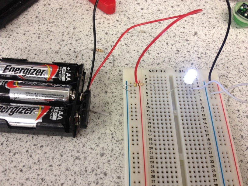
I then took it a step further by using a LDR to see if I was able to develop my knowledge. Below is a picture demonstrating this.