S2 Create and interpret circuit diagrams

This area of the audit has been marked at '1' meaning very little knowledge if not any at all.
__________________________________________________
__________________________________________________
What I have learnt and what I understand now
During our session today we were introduced to Circuit Wizard which is a program that enables you to create circuit diagrams. I discovered that a circuit diagram is pretty much what it says on the tin, it is a diagram that shows a circuit and how it will function. It also uses universal symbols that represent the components used to create circuits. Although, so far we have only been taught how to create a circuit diagram using software, I soon realised that you can in fact merely draw a circuit diagram using the same symbols so there is no difference or right or wrong and I learnt this at a later date.
So now I know what a 'Circuit diagram is' I felt as if I then needed to become familiar and understand what these symbols represented. First of all I have just been looking at google and soon found that there are certainly a vast amount of different components and symbols! I felt a bit overwhelmed by it all so I decided to have a look at Bitesize to see if there was any way I could learn the most commonly used symbols in Design and Technology. Low and behold I came across a very useful table which showed all of these common components/symbols and as a result it has helped me with my development.
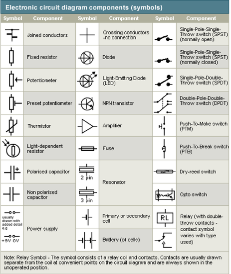
This table really helped me to understand all of the symbols and components that were included programmed in the Circuit Wizard software. At first when I was exploring the programme all of the symbols were completely foreign to me because of my previous lack of experience. However, when I researched this area on Bitesize I discovered that I started to gain more confidence and recognised this symbols without having to refer back to the table. I knew that this was a good starting point in developing my understanding in this area of the audit so I was pleased that I used Bitesize yet again as a source that supported my learning.
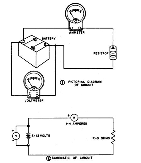
Through my research I have also noticed that some circuit diagrams are drawn differently like the image below. I think that this may be dependent on the age you may be teaching the content to and their abilities, but I think it is a useful thing to document and consider when teaching. As a learner it is also useful to know the other ways in which these can be created so that I am able to interpret all of them.
Through my research I have also noticed that some circuit diagrams are drawn differently like the image below. I think that this may be dependent on the age you may be teaching the content to and their abilities, but I think it is a useful thing to document and consider when teaching. As a learner it is also useful to know the other ways in which these can be created so that I am able to interpret all of them.
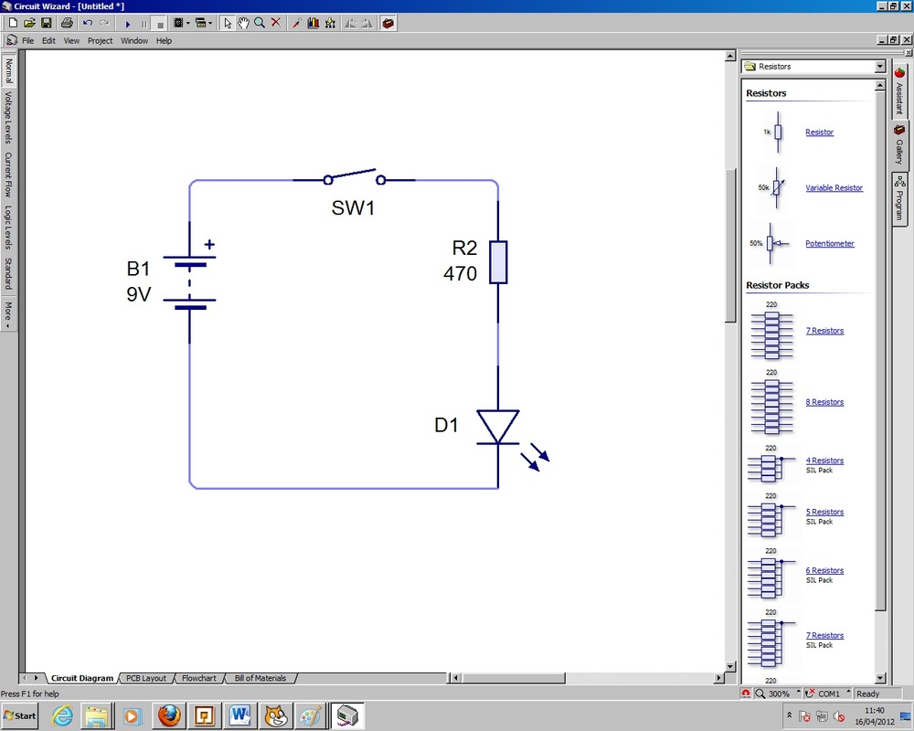
Here are some examples of me using circuit wizard. These are just practice and mock circuits that I have created just to familiarise myself with the programme.
I felt that Circuit Wizard is pretty user friendly and it did not really take too long for me to get the hang of it.
The best thing that I have taken away with this exploring and engagement task is that it has really been able to help me learn more and develop my understanding of how a circuit works. I also felt that having wires that connected the components and the power supply also allowed me to see the flow of the circuit functioned. I found it really useful to have a look at the example projects that they used on software it gave me an idea of how I could build my own.
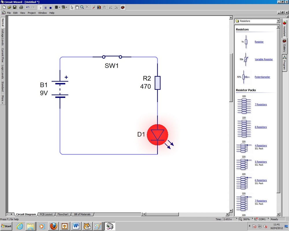
Another aspect that I have taken away with me from this task is that as I progressed and created several more and different circuits I began to notice that there were certain common principles that can be transferred and applied to when you are creating other circuit diagrams. Regardless of the intentions you have for a circuit each circuit will have the Plus volts (V+) at the top and the ground (0) a the bottom of the diagram. At least one component will be connected to the plus and ground volts in order for the circuit to work. If broken then no components will work because electricity is unable to flow through the wires.
So to conclude my understanding on what I have learnt so far in this area of the audit is that creating a circuit means either by using Circuit Wizard or drawing it by hand to display a proposed diagram with all of the symbols and components. Interpreting the circuit means that you are familiar and understand the universal symbols and components the circuit includes.
___________________________________________________________________
Analysis of new gained knowledge and the next step
To begin with I did not know anything about this area of the audit and for that reason I marked it as a '1' meaning very little knowledge if not any at all. Now I can confidently say that I have obtained some comfortable knowledge.
As a learner I was most successful when I was left alone to my own devices to explore the software in more depth. I have noticed that feel quite comfortable using new software in most circumstances, perhaps this is because within my degree I was constantly using the computer and learning new software so it is almost as if it is second nature. However, I do genuinely feel that circuit wizard is very user friendly especially if it is aimed at young people.
In addition, I found that Bitesize was another source that supported my learning but I do not want to become in the habit of relying on it all the time because I feel that this can enable you as a learner to become lazy. I do not want this to a primary source that aids my development and for that reason I do feel as if I need to explore other mediums to help me. In regards to this actually I did find myself learning a great deal more when I experimented further and also spent more time on it. This is clear that the more time you spend the more your able to be confident in areas that are at first overwhelming.
Although I did find this task successful in terms of my progression, there were times when I struggled to grasp what all of the symbols and components meant and did. I think like anything though this is going to take time, but then I later realised that there is not a great need to know every single component because not all of them will be used in schools.
My next step now is to create a circuit diagram using the software for my own project. This not only will be good practice but can hopefully help me with my own work and the development.
___________________________________________________________________

Further Development
My Circuit Diagram
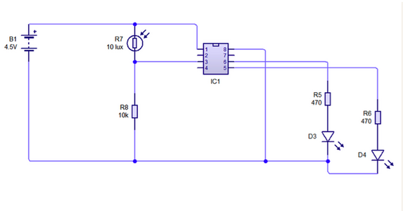
This is my circuit diagram that I created for my own project in the systems and controls module.
This task has not only helped me even further with my development in this area but also it has allowed me to grasp even more of an understanding about how my circuit will work. Another factor that was extremely useful was that I was then able to identify and potential faults in my work.
as allowing me to grasp a better understanding as to how my circuit will work.
The only important thing that I needed to consider when creating this circuit using this software was that the PIC CHIP didn't actually represent the same PIC CHIP that I was using within my board. The inputs and out puts are in different orders.

This is what the PIC should look like on the diagram. So when I was building my circuit I needed to refer to these input/outputs otherwise this would have lead to faults later on in the process.